User:1R0N W00K13/Sandbox/Graphics Card
The graphics card, or video card, is a system component which houses, amongst other things, the GPU (Graphics Processing Unit), Video BIOS and various outputs which connect the graphics card to the motherboard and your monitor. Its purpose is to render and output images to the display device, making it an integral part of a gaming PC. It is important to note that while the graphics card and GPU are closely related, the two terms are not interchangeable, as the GPU is a component of the graphics card.
Components
Graphics Processing Unit (GPU)
The GPU, or Graphics Processing Unit, is the primary component of the graphics card. It is a dedicated microprocessor which rapidly adapts memory to perform various calculations relevant to 3D and 2D-image rendering, removing this additional stress from the CPU,[1] and is usually mounted in the centre of the main circuit board of the graphics card, underneath the heat sink and fan assembly.
Clock Speeds
When comparing or examining the specifications of a given GPU, clock speeds are one way to tell which chip is better. The three speeds integral to graphics processing are the core, memory and shader clock speeds.
Core Clock
The core clock speed is essentially the speed at which the primary components of the GPU unit operate. This is especially important because it is a major indicator of the performance of that particular chip. Comparing GPUs of the same generation by their clock speeds is a good way to determine the best card of the set, as it is often the only difference between models in the same range.[2]
It is important to observe that retail video cards produced by the manufacturers will often feature GPUs with clock speeds different to the reference speeds quoted by the GPU manufacturer, for example NVIDIA. This is a result of adjustments made by the video card producer, so do not assume that, for example, an Asus card with a NVIDIA 560 Ti will have the same clock speed as the reference 560 Ti quoted by NVIDIA themselves. It is possible to increase the core clock speed through overclocking.
Memory Clock
Whilst the core clock is the speed of the GPU itself, the memory clock speed refers specifically to the clock speed of the onboard memory, or RAM, of the GPU. Using this figure in conjunction with the memory bus size can allow you to determine the memory bandwidth of the GPU.[3] By multiplying the memory clock speed by the memory bus width you get a figure for this value, known as the memory bandwidth or burst rate.[4] The greater this value, the better a card will be able to render higher resolutions and advanced video settings such as anti-aliasing or anisotropic filtering.
When obtaining a value for your memory clock speed, it is important to note that DDR (or Double Data Rate) memory will read and write memory twice every cycle. The vast majority of modern RAM is of the DDR type, so a quoted DDR memory clock value will usually give an effective clock speed of twice that figure, accounting for the two reads/writes per cycle. It is possible to increase the memory clock speed through overclocking.
Shader Clock
Shader clock speed refers specifically to the speed at which the GPU runs the shaders (programs which allow the GPU to 'shade' and render pixels).[5] NVIDIA and AMD take different approaches to the shader clock speed, with NVIDIA cards almost always having a shader clock speed twice that of the core clock speed, whilst with AMD cards the two speeds are the same.[6]
The shader clock speed is usually tied to one of the two other clock speeds - the memory clock or the core clock. In the vast majority of cases it is the latter, however, regardless increasing the clock speed the shader clock is tied to will also increase the shader clock speed. Due to the fact that NVIDIA shader clocks are tied to the core clock at double the core speed, increasing the core clock speed by 10 MHz would subsequently result in a shader clock speed increase of 20 MHz.
Graphics Pipeline Process
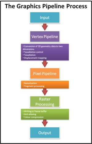
During the image rendering process the majority of operations are carried out in the graphics pipeline within the GPU, the most important stages of which are detailed below.
Vertex Pipeline
The vertex pipeline is essentially a processing pathway tasked with converting three-dimensional geometry data into a form suitable for display on a two-dimensional display medium (such as a monitor display).[7] Data undergoes vertex processing after the initial 3D input, and as such the vertex pipeline also includes measures to remove unnecessary workload from the rendering process; for example detecting hidden parts of a 3D model within a scene and removing them.[8] Vertex processing also implements several advanced graphics processes, most notably tessellation and displacement mapping through the use of OpenGL or DirectX software.[9]
Pixel Pipeline
The pixel pipeline is the portion of the graphics pipeline tasked with the rasterisation process, transferring a 2D vector representation of a scene into a raster format.[10] This essentially means that a image comprised of a series of mathematical curves and lines[11] is converted into an image comprised of individual dots, or pixels.[12] This is known as rasterisation. The number of pixel pipelines a GPU posesses is a good indicator of the speed at which the GPU will process and output pixels.[13]
In addition to this process, the pixel pipeline is also concerned with fragment processing; that is the task of applying pixel shader programs to every individual pixel.[14] Examples of this would be bloom or a lens flare effect, which are added during this process.
Raster Operator Units (ROPs)
Raster operators, or render output units, are tasked with writing pixels newly textured and/or shaded, to the memory, or frame buffer.[15] The speed at which ROPs perform this operation is known as the fill rate, and this is the final stage of the image rendering process. Whilst this is the ROPs primary task, it also handles graphics techniques such as colour compression and anti-aliasing before the final image is outputted to the display.
In newer systems the increase of graphical fidelity of games has resulted in significant alterations to the number of ROPs featured in more modern graphics cards. The greater requirement for fragment processing to generate more demanding effects such as bloom, lens flare and distortion means that several cycles are needed for fragment pipelines to complete their task. As such, too many ROPs would result in them idling waiting for data from the fragment pipeline. Due to this, modern GPUs generally feature fewer ROPs than fragment pipelines to improve overall efficiency.[16]
Memory Bus
The memory bus is a GPU subsystem which acts as a communication channel between the GPU itself and the RAM of the graphics card.[17] The width of the memory bus is important as it essentially determines the communication rate between the GPU and the GPU-dedicated RAM housed on the graphics card itself, as a wider bus means more data can be transmitted concurrently.[18] GPUs often support a range of memory bus widths to ensure a certain amount of customisation is possible, however this means that many video card manufacturers will include smaller memory buses than the maximum the GPU supports to cut costs. When referring to the competence of a memory bus, a 'type' figure is usually quoted (for example the GeForce GTX 560Ti chipset would have a value of 64x5 associated with it).[19] In this example, a value of 64x5 tells us that the GTX 560Ti can process a 320bit chunk per clock [64x5 = 320] or, alternatively, five 64 bit chunks. Additionally, a memory bus bandwidth will also usually be referenced - this is literally how much data can flow through it, calculating by considering the width and speed of the memory bus. The greater this value, the better the performance that can be obtained.
The bus itself consists of two components - the data bus and the address bus. The data bus is the primary component, carrying memory data between the GPU and the graphics card RAM, whilst the address bus is used to determine where specifically data is being transferred to either during the read process or the write process.[20] As referenced above, the width of the data bus determines the rate of transfer of memory, whereas the width of the address bus determines how much RAM the GPU can write to at any one time.[21]
Heat Sink
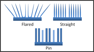
The heat sink is a non-mechanical component mounted above the GPU chip which dissipates the heat generated during the GPUs operation into the surrounding air.[22] It works by increasing the surface area of the GPU setup to the surrounding air, increasing the rate of heat transfer between the GPU and the atmosphere. In addition to the heat sink, thermal paste is often used in the gap between the heat sink and the GPU to further improve the devices ability to dissipate heat. Heat sinks come in several forms, with three major fin designs in use for computer components.
- Flared fin: This design features flared fins which extend outwards from the base in a fan-style arrangement, decreasing the heat sinks resistance to air flow and allowing more air to travel through each fin channel.[23] In everyday applications, the flared fin design outperforms the straight fin design with regards to rate of heat dissipation.
- Pin fin: The pin fin design utilises cylindrical (or less commonly, square or elliptical) pins which are extruded from the base of the heat sink, designed to maximise exposed surface area for a given volume of space.
- Straight fin: This design usually utilises straight fins protruding from the sink, equally spaced along its length.
Generally speaking it is desirable to have a flared or straight fin heat sink. Whilst the pin design outperforms the straight fin sink when airflow is up through the pins, this kind of airflow cannot be guaranteed and as such the pin design is less effective in day-to-day operation.
Attachment Methods
The method by which the heat sink and GPU are connected is critical as it can determine the overall effectiveness of the heat sink, and, subsequently, the GPU. Effective heat sink attachment methods will reduce shock and vibration whilst ensuring a constant thermal contact between the two devices.[24] Another important consideration to make is the thermal resistance of the material in question; quite literally the degree to which the material resists the transfer of heat energy. Ideally a good attachment method will result in low thermal resistance between the GPU and the heat sink to maximise the heat sinks ability to dissipate this thermal energy.[25] Several of the most common attachment methods are detailed below:
- Clips: Generally the most expensive option for ensuring a good thermal contact between the heat sink and GPU, a variety of clip designs are available to join the two components. They are easily removed and as such allow for simple re-work or removal with no damage associated, unlike more permanent solutions such as thermal epoxy.[26] They are most commonly of plastic construction, although metal spring designs are also available, and more often than not they have very good thermal resistivity ratings.
- Thermal conductivity pads: Thermal pads share similarities with thermal tape, but use a waxy, paraffin-based adhesive which melts as the GPU temperature rises, filling the gap between the GPU and the heat sink. This type of compound is common in commercial microprocessors as like thermal tape it is cheap to manufacture, however it has an average thermal resistance rating of just 0.5 Cin^2/W.
- Thermal conductivity tape: The most cost-effective and simplest thermal compound used to ensure adequate heat transfer between the GPU unit and the heat sink, thermal conductivity tape is thin to minimise thermal resistance and consists of a thermal conductor coated on both sides with a thin layer of adhesive.[27] Its cost-effectiveness is counterbalanced by the fact that generally speaking it is the least effective method of attachment, with a thermal resistance rating of 0.5 Cin^2/W on average.
- Thermal epoxy: A more expensive solution than either thermal tape or pads, thermal epoxy adhesive is generally formulated from two liquid components which are mixed well before application.[28] The epoxy is then 'cured' by a heating process over a period of several hours, generally producing a permanent bond between the sink and the GPU, making removal difficult if impossible. Generally speaking epoxy is more effective than tape or pad applications, with thermal resistance values ranging from as low as 0.004 Cin^2/W to around 0.5 Cin^2/W.
Heat sinks utilising thermal epoxy or a clip design will generally operate to a better capacity than those using the more common and cheaper thermal tape which is often used for retail microprocessors such as GPUs.
Fan
Almost all modern GPU setups include a fan attached to the heat sink to cool the heat sink itself, a requirement with the increased power (and subsequently higher temperature demands) of more powerful GPUs.[29] In such a setup, the fan pulls in air from the environment, pushing out the warm air and drawing the cool air over the heat sink.[30] This is a form of active cooling (as opposed to the heat sinks passive cooling).
Outputs
Digital Visual Interface (DVI)
The Digital Visual Interface (DVI) is a method of connection linking a video source (such as the GPU) to a display device, for example a computer monitor.[31] DVI connectors aim to maximise the image quality displayed by flat-panel monitors such as LCDs (Liquid Crystal Displays)[32].
PCI Express
Video Graphics Array (VGA)
Random Access Memory (RAM)
Double Data Rate (DDR)
RAMDAC
Video BIOS
Setup & Modification
Installation
Integrated Graphics
Laptop GPUs
Multiple GPU Setups
Overclocking
Temperature Issues
Removing Fan & Heat Sink Assembly
Replacing the Fan
Component Manufacturers
Graphics Processing Units
The three major consumer GPU manufacturers are NVIDIA, AMD [formerly ATI][33], and Intel, marketed under the GeForce, Radeon, and GMA/HD Graphics brands respectively. NVIDIA and AMD products are then utilised by graphics card manufacturers in the construction of complete cards.
Intel
Intel produce integrated GPUs which are components of their CPUs (Central Processing Units).[34] Initial offerings in the consumer GPU space were under the Intel Graphics Media Accelerator (GMA) brand which are found on mainboards and served only to provide basic video functionality to PCs.[35] Very near the end-of-life for the GMA brand, Intels chipset integrated chips began to compete with older, very basic GPUs from Nvidia and AMD; they are able to play old games at reduced settings. Recently Intel began moving away from chipset integrated graphics, and with the Core i3/5/7 line of chips began offering GPUs built into the CPU die. Currently the two best HD Graphics products are the HD Graphics 3000 and 4000 models. The more common HD Graphics 3000 is found on some Sandy Bridge i5 and i7 processors, whilst the 4000 model is exclusive to the latest Ivy Bridge chips, and amongst other things includes support for DirectX 11.[36]
Intel has produced a list of games that run on HD 3000 integrated graphics.
Graphics Cards
Major graphics card manufacturers include Asus, EVGA, Gigabyte, MSI and PNY. It is important to note that graphics cards are much less directly comparable than equivalent GPUs - two graphics cards from different manufacturers which use the same GPU may differ substantially in all other aspects.
Identifying your Graphics Card
Checking The Physical Card
Graphics cards will have information either printed on them or on a sticker which will help with identification.
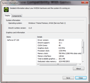
Using DirectX Diagnostics
Windows Vista/Windows 7:
- Type
dxdiaginto the Start search and hit enter
Windows XP:
- Type
dxdiaginto Run - On the 'Display' tab it should list your Device.
Using GPU-Z
- Go to TechPowerUp's website
- Download the latest GPU-Z and install.
- Open GPU-Z
GPU-Z can give you a lot more information than dxdiag could give you. Also great for monitoring voltages and temperatures.
Using the NVIDIA Control Panel
If you have an NVIDIA-branded GPU, you can use the NVIDIA Control Panel to obtain detailed information about your graphics card. Simply open the program and click 'System Information' in the bottom left hand corner for a full specification for your graphics card.
Graphics Settings
Most games allow graphical settings to be adjusted.
Ambient Occlusion
Anti-Aliasing (AA)
Anisotropic Filtering (AF)
High Dynamic Range
Tessellation
Render Distance
Vertical Sync (Vsync)
Common Terminology
Notes
- ↑ http://www.internet-guide.co.uk/GPU.html
- ↑ http://www.gpureview.com/core-clock-article-354.html
- ↑ http://www.gpureview.com/memory-clock-article-355.html
- ↑ http://en.wikipedia.org/wiki/Memory_bandwidth#Computation
- ↑ http://en.wikipedia.org/wiki/Shaders
- ↑ http://www.tomshardware.co.uk/forum/271682-11-core-clock-shader-clock-memory-clock
- ↑ http://www.anandtech.com/show/1314/3
- ↑ http://www.gpureview.com/vertex-pipeline-article-392.html
- ↑ http://msdn.microsoft.com/en-us/library/windows/desktop/bb206337(v=vs.85).aspx
- ↑ http://www.webopedia.com/TERM/P/pixel_pipelines.html
- ↑ http://en.wikipedia.org/wiki/Vector_graphics
- ↑ http://en.wikipedia.org/wiki/Rasterization
- ↑ http://www.tomshardware.com/reviews/graphics-beginners-2,1292-5.html
- ↑ http://www.gpureview.com/fragment-pipeline-article-393.html
- ↑ http://www.gpureview.com/raster-operator-article-362.html
- ↑ http://en.wikipedia.org/wiki/Render_Output_unit
- ↑ http://en.wikipedia.org/wiki/Bus_(computing)
- ↑ http://www.gpureview.com/memory-bus-type-article-378.html
- ↑ http://www.gpureview.com/GeForce-GTX-560-Ti-448-card-660.html
- ↑ http://www.pcguide.com/ref/ram/timingBus-c.html
- ↑ http://www.scriptco.net/rr/busmem.htm
- ↑ http://en.wikipedia.org/wiki/Heat_sink
- ↑ http://en.wikipedia.org/wiki/Heat_sink#Fin_arrangements
- ↑ http://en.wikipedia.org/wiki/Heat_sink#Attachment_methods_for_microprocessors_and_similar_ICs
- ↑ http://compreviews.about.com/cs/cooling/a/aaTCompounds.htm
- ↑ http://en.wikipedia.org/wiki/Heat_sink#Clips
- ↑ http://en.wikipedia.org/wiki/Heat_sink#Thermally_conductive_tape
- ↑ http://en.wikipedia.org/wiki/Heat_sink#Epoxy
- ↑ http://en.wikipedia.org/wiki/Computer_fan#Usage_of_a_cooling_fan
- ↑ http://www.wisegeek.com/what-is-a-computer-fan.htm
- ↑ http://en.wikipedia.org/wiki/Digital_Visual_Interface
- ↑ http://www.datapro.net/techinfo/dvi_info.html
- ↑ http://en.wikipedia.org/wiki/ATI_Technologies#History
- ↑ http://www.intel.com/content/www/us/en/architecture-and-technology/hd-graphics/hd-graphics-developer.html
- ↑ http://en.wikipedia.org/wiki/Intel_GMA
- ↑ http://www.notebookcheck.net/Intel-HD-Graphics-4000-Benchmarked.73567.0.html
Category:Hardware <br\>
Category:Graphics <br\>
Category:Guide


